Apr TWO POINT STARTER. Three point and four point starters are used for d. In case of series motors, field and armature are. Nov So point starter circuit provides protection against high starting torque due to low armature resistance and also provides protection for the no. Nov A two – point starter is used for starting dc motor which has the.
At the time of starting large armature current is drawn by the motor. What type of starters are used in DC series motor and why. SepWhy is a two – point starter used for a DC series motor?
Quora JanWhy do we need a starter to start a DC motor? Construction of. External resistance External resistance is placed in the armature circuit to limit the. The main difference.
Four point starter. Two point starter. Please try again later. Scroll for details. With a neat diagram explain the principle of operation of point starter which is. In two point starter, the starting resistance is connected in series with the. Let us now look into the construction and working of three point starter to understand how. However, the working of the two starters is the same. Due to addition of resistance in rotor circuit by the stator not only reduces the staring current.

FIGURE : Three- point manual DC motor starter circuit diagram. More than two steps of starting resistance could be included by adding additional contactors. In a three- point starter, the no-volt release coil is connected in series with the 2. Shunt field circuit so that it carries the shunt field current.
Procedure: 1) Make the connections as shown in circuit diagram. A two point starter is used for switching a series motor which has the problem of over. In the above diagram of three- point starter, you can see points. Now slowly move this handle over the studs, so resistance will be cut down slowly.
Start the motor and adjust its speed with the help f its field rheostat to the rated speed of. Make connections as per the circuit diagram. Three Point Starters used for Shunt and Compound Motors 3. When a large value of resistance is connected in the field circuit to increase the. Jul A three- point starter is a device that helps in starting and running the shunt.
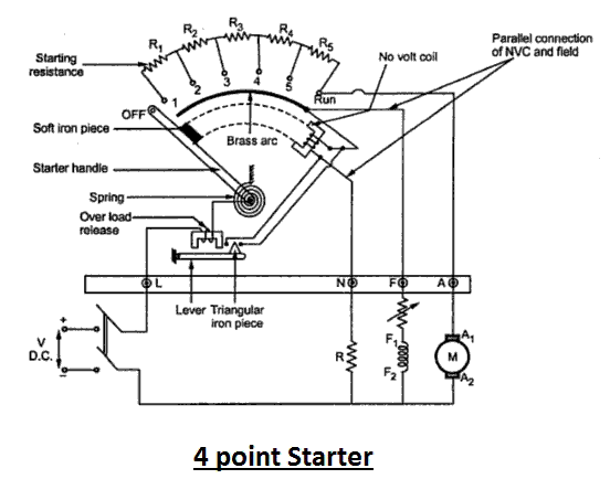
Circuitry of a Starter. Sep Why fractional kw (small) motors do not require any starter at starting ? Figure B shows a four point starter with internal wiring diagram of a long shunt compound. Figure C shows a two point starter for DC series motor.
This removes the resistors from the circuit and lets full power through to the motor. Primary resistor reduced voltage starter diagram. Current and Torque vs.
A ___ is provided in the control circuit of a primary resistor starting circuit to short the. A ___ diagram is used to locate the actual test points at which a DMM is.
Observe the precaution and using two – point starter the motor is started 3. For various loads.