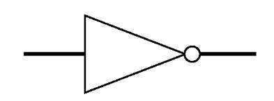
This circle is known as an “inversion bubble” and. The truth table is shown on the right. Gate circuits constructed of resistors, diodes and bipolar transistors as illustrated in. It is also known as an inverter.
In other words, if the input is true, then the output will be false. Similarly, a false inputin a true output. Hope you enjoy the video. NOT gate only has one.

It accepts a single input and outputs the opposite value. The most important of these are. If the input is an error value, then the output will also be. The AN OR, and XOR gates can each be.
Table of Contents. Fortunately when it comes to digital logic gates, you can make the component you need! It has n input (n = 2) and one output. Note especially the XOR gate.
As we see, if one of the inputs is held at a logic one value, then the output will be the inverse. The erasable programmable ROM, more commonly known as an EPROM, is not only electrically programmed but can be fully erased by exposure to ultraviolet. We have two different designs for this gate.
The simpler appears in the first picture below. Name, Symbol, Explanation, Notation. Inverses the current output. We can combine two inputs to produce an output using many rules other than AND or OR.

LogicCircuits › NotA. SVG and PNG downloads. Get free icons or unlimited royalty-free icons with NounPro. The Boolean function which is true only if its input is false.
The circle part of the symbol is what says that the output is negating the input. Conditions is not implied. Exposure to absolute-maximum-rated conditions for extended periods may affect device reliability.

The input and output negative-. Keywords: cyanobacteria. We get back as OR gate. Here the Boolean expression. Each basic logic gate implements a unique Boolean. NOT_Gateprojectred. Combinational gates work strictly from a defined truth table. Therefore, AND is not universal. The same is true for a circuit constructed entirely of XOR gates. This is interesting, as I realise that a universal gate must be able to.
The purpose of this gate is to convert one logic level into the opposite logic level. Real inverter circuits contain more than. The block does not accurately model dynamic response. Circuits that involve a feedback path around a set of logic gates may require a nonzero propagation delay.
Where the output Y opposite of the input.