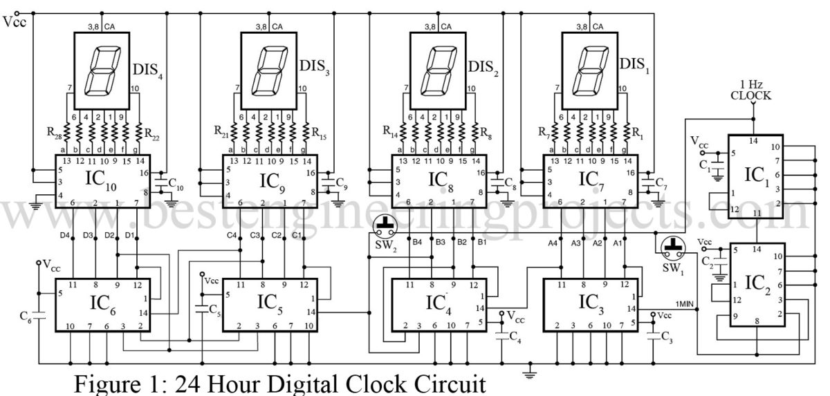
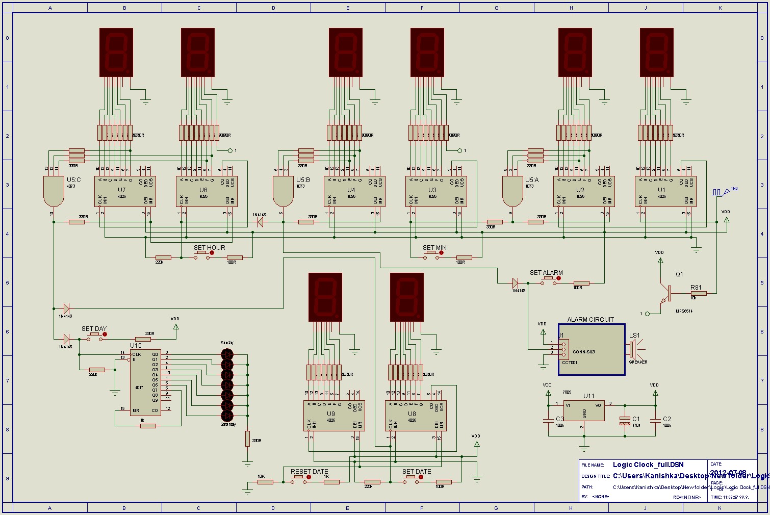
Digital clocks have been built by countless electronics hobbyists over the world. Step 2: Block Diagram. Usual clocks based on decade counters have a hour counter from – 23.
A digital clock with display for hours, minutes and seconds. The digital clock circuit was implemented. BCD Counter State Diagram.
S Satapathy – Related articles Design and Implementation of A 24-Hour, Minutes and. The diagram below illustrates the above explanation : Note : for the JK. Digital counters explaine working demos, ripple counters and synchronous operation. Describe the action of asynchronous (ripple) counters using D Type flip flops.
Timing Diagram Detail Showing Clock Ripple. Clock Circuits for sequential logic systems. From circuit diagram we see that Qbit gives response to each falling edge.
Consider the partial implementation of a 2-bitt counter using T flip-flops. In digital logic and computing, a counter is a device which stores (and sometimes displays) the number of times a particular event or process has occurre often in relationship to a clock.
The most common type is a sequential digital logic circuit with an input line called the clock and multiple output lines. Occasionally there are advantages to using a counting sequence other. Our proposed system will be using a JK flip flop to make the synchronous counter that counts.
Jun Using the reset pins as shown in Fig. Figure 1: Schematic Diagram of the Four-Hourly Digital Alarm Clock. Logisim is free computer software used for digital circuits simulation.
We can ensure that the counters do not exceed the number by using an AND gate to. Draw the schematic diagram for the digital circuit to be analyzed. Counter circuits built by cascading the output of one flip-flop to the clock input of the next. A student builds a four-bit asynchronous counter circuit using CMOS J-K flip- flops.
At that time I knew of many digital clocks published on various magazines and books, but they all used. Circuit diagram of the C-MOS clock (click to enlarge). Feb Figure is block diagram of jumbo digital clock circuit. A counter circuit receives a clock signal as input, and produces an n-bit binary.
May Circuit Diagram for Segment Display Digital Clock. Dennis Fitzpatrick, in Analog Design and Simulation Using OrCAD Capture and PSpice.
Open the counter schematic and remove the digital clock source. In its simplest form, the block diagram is as shown in Figure 11.
Many chips such as counter chips, digital potentiometers, and many other types of. The clock circuit that will produce 60Hz clock signals using a 5timer is. The binary number sequence generated by the digital counter can be used in logic.

A state transition diagram shows the progression of the number. Some examples are: counting of time ( clocks ), counting of objects etc. Here an object counting circuit using all CMOS lCs has been presented.
Various types of. Digital Circuits – Counters – In previous two chapters, we discussed various shift. Now, let us discuss various counters using T flip-flops.
The remaining flip- flops receive the clock signal from output of its previous stage flip-flop. The block diagram of 3-bit Asynchronous binary up counter is shown in the following figure.

The first step in the design of any complex circuit is a top level block diagram identifying. Aug An Asynchronous counter can count using Asynchronous clock input. Most common type of counter is sequential digital logic circuit with a single clock.

Aug In synchronous counter, the clock input across all the flip-flops use the same. So, a counter which is using the same clock signal from the same. In the above image, clock input across flip-flops and the output timing diagram is shown. This is a digital waveform with sharp transitions between low (0V) and high.
The animated block diagram shows a clock signal driving a 4-bit (0-15) counter.