A3120 Circuit Diagram: Unveiling the Secrets of this Essential Component
In the world of electronics, circuit diagrams are the unsung heroes that help engineers and hobbyists bring their innovative ideas to life. Among the many components used in these diagrams, the A3120 circuit is a crucial element that plays a significant role in ensuring proper functionality. In this comprehensive guide, we will delve deep into the A3120 circuit diagram, exploring its intricacies, applications, and the importance of understanding its layout.
Introduction
The A3120 circuit diagram is a critical component in the world of electronics, known for its ability to provide electrical isolation and high-speed switching. In this article, we will explore the intricacies of this component, its applications, and how to effectively decipher its diagram.
What is the A3120 Circuit?
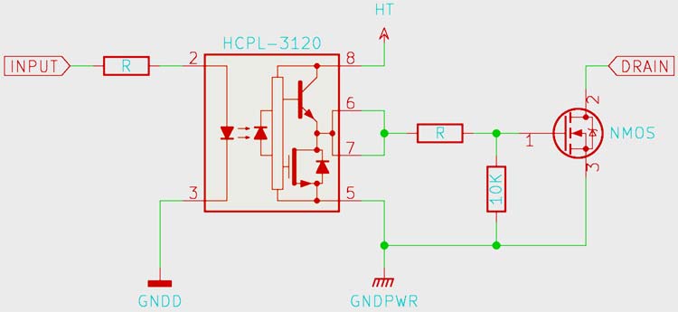
The A3120 circuit, also known as an optocoupler, is an integrated circuit designed for high-speed digital interface applications. It consists of an LED (Light Emitting Diode) and a phototransistor enclosed in a light-sensitive package. This component is used to transmit signals between two electrically isolated circuits.
Components of the A3120 Circuit
3.1. LED (Light Emitting Diode)
The LED in the A3120 circuit serves as the input side of the optocoupler. When current flows through it, it emits light, which is then directed towards the phototransistor.
3.2. Phototransistor
The phototransistor is the output side of the A3120 circuit. It responds to the light emitted by the LED and allows current to pass through when illuminated.
3.3. Internal Oscillator
The A3120 circuit also contains an internal oscillator that ensures proper functioning, making it an essential component in various applications.
Working Principle
4.1. Input and Output
The A3120 circuit operates based on the principle of photoconductivity. When the LED emits light, it strikes the phototransistor, causing it to conduct electricity and allowing the signal to pass from the input side to the output side.
4.2. Isolation Barrier
One of the primary advantages of the A3120 circuit is its electrical isolation capability. This isolation barrier ensures that there is no direct electrical connection between the input and output sides, protecting sensitive components from voltage spikes and noise.
Applications of A3120 Circuit
5.1. Motor Control
A3120 circuits are frequently used in motor control systems, where they help in isolating control signals from high-power circuits, preventing interference.
5.2. Power Supply Regulation
In power supply regulation, A3120 circuits are used to monitor voltage levels and provide feedback for precise control.
Advantages of Using A3120 Circuit
The A3120 circuit offers several advantages, including:
- Electrical Isolation
- Fast Response Time
- Compact Size
- High Reliability
Disadvantages and Limitations
Despite its many benefits, the A3120 circuit has limitations, such as limited voltage and current ratings, which may restrict its use in high-power applications.
Understanding the A3120 Circuit Diagram
8.1. Block Diagram
The A3120 circuit diagram typically includes a block diagram that illustrates the major components and their connections.
8.2. Pin Configuration
Understanding the pin configuration is crucial for successful circuit design and integration.
8.3. Internal Connections
Exploring the internal connections within the A3120 circuit provides valuable insights into its functionality.
How to Read A3120 Circuit Diagrams
9.1. Identifying Components
Learning to identify the various components within the diagram is the first step in reading A3120 circuit diagrams.
9.2. Tracing Signal Flow
Tracing the signal flow from input to output helps in understanding the circuit’s operation.
Common Mistakes in A3120 Circuit Design
Avoiding common design mistakes is essential to ensure the circuit functions as intended.
Tips for Successful Implementation
Implementing the A3120 circuit effectively requires careful planning and attention to detail.
Troubleshooting A3120 Circuit Issues
Troubleshooting is an essential skill when working with A3120 circuits, as it helps identify and rectify problems.

Future Developments
The field of optoelectronics is continually evolving, and we can expect to see advancements in A3120 circuit technology in the future.
Conclusion
The A3120 circuit diagram is a fundamental element in electronics, offering electrical isolation and fast switching capabilities. Understanding its components, working principle, and applications is crucial for successful circuit design and implementation.
FAQs
- What is the purpose of the A3120 circuit in motor control systems?The A3120 circuit in motor control systems provides electrical isolation and ensures precise control of the motor.
- Can the A3120 circuit be used in high-power applications?The A3120 circuit has limitations in terms of voltage and current ratings, making it more suitable for low to moderate-power applications.
- How do I troubleshoot issues with the A3120 circuit?Troubleshooting A3120 circuit issues involves checking connections, ensuring proper power supply, and inspecting component integrity.
- What are the primary advantages of using the A3120 circuit?The main advantages include electrical isolation, fast response time, compact size, and high reliability.
Enhancing Circuit Protection: Guarding Against Reversed Voltage Polarity
In the world of electronics and circuitry, safeguarding against reversed voltage polarity is paramount. This article will delve into the importance of functional diagrams, power output stages, optocouplers, and more to protect circuits from potential disasters.
Understanding the Functional Diagram
Let’s start by understanding the functional diagram, a crucial element in circuit design. The functional diagram illustrates the flow of current within a circuit. One significant concern is ensuring that all the current is efficiently transferred into the MOSFET (Metal-Oxide-Semiconductor Field-Effect Transistor) while the diode is turned off completely.
The Role of Optocouplers
Optocouplers, often referred to as optoisolators, play a pivotal role in circuit protection. These devices are designed to electrically isolate one part of a circuit from another while allowing optical communication between them. This isolation is vital in preventing reversed voltage polarity from causing damage.
Optocouplers in Power IGBTs and MOSFETs
In modern electronics, power IGBTs (Insulated Gate Bipolar Transistors) and MOSFETs are commonly used in motor control inverter applications. Optocouplers are ideally suited for driving these power components. They provide a secure connection between the control circuit and the power stage, reducing the risk of polarity-related issues.
Amp Output Current IGBT Gate Drive Optocoupler Data Sheet
For those seeking detailed specifications on these optocouplers, the Amp Output Current IGBT Gate Drive Optocoupler Data Sheet is a valuable resource. It offers comprehensive information on how these devices can protect your circuits effectively.
Circuit Diagrams and Protection
To further fortify your circuits against reversed voltage polarity, having access to comprehensive circuit diagrams is essential. These diagrams provide a visual representation of the components and their connections within a circuit.
The Importance of Diodes
One essential component for circuit protection is the diode. Diodes ensure that current flows in one direction and blocks it in the opposite direction. External diodes, when strategically placed, can be part of the solution to protect against reversed voltage polarity.
Gate Capacitance and Circuit Recommendations
Gate capacitance is an inherent characteristic of many electronic components, including MOSFETs and IGBTs. Understanding how gate capacitance affects your circuits is crucial. Some circuits require special attention to mitigate potential issues related to gate capacitance.
Crystal View Displays and Ground Reference Nodes
In some applications, having a high-contrast display can be critical. The Wide Color-Enhanced Crystal View display is a unique solution that delivers exceptional clarity. Additionally, it’s important to identify the ground reference node in your circuit schematic, as it serves as the basis for voltage measurements and circuit protection.
Analyzing Circuits with Nodal Analysis
To gain a deeper understanding of circuit behavior, nodal analysis can be an invaluable tool. This technique helps analyze the flow of current at various nodes within a circuit, enabling you to identify potential issues and optimize performance.
Modified Sine Wave Signal Generator
For those interested in generating modified sine waves, a schematic diagram of a 600VA numeric UPS circuit can be a valuable resource. Understanding how to check pulse voltage at the gate and source in MOSFETs and IGBTs is crucial for maintaining circuit integrity.
Wiring Diagrams and Impedance Analysis
Wiring diagrams are essential for circuit assembly and troubleshooting. They provide a visual guide to connect components correctly. Additionally, impedance analysis, often depicted in phasor diagrams, helps engineers understand how different elements in a circuit affect its performance.
Safety Requirements and Block Diagrams
Ensuring safety in electronic systems is paramount. Specification of safety requirements, often illustrated in structural schematic block diagrams, helps engineers design circuits that comply with industry standards and regulations.
Integrated Circuits and Datasheets
Integrated circuits (ICs) are the building blocks of modern electronics. Accessing datasheets for specific ICs provides detailed information on their functionality, enabling engineers to integrate them effectively into their designs.
Conclusion
In the ever-evolving field of electronics, protecting circuits from reversed voltage polarity is a top priority. Understanding functional diagrams, utilizing optocouplers, and employing circuit protection strategies, including diodes and gate capacitance management, are essential steps. Additionally, leveraging resources such as circuit diagrams, nodal analysis, and datasheets empowers engineers to design robust and secure electronic systems. By prioritizing circuit protection, we ensure the longevity and reliability of our electronic devices and applications.